0-10V Analogue Input Simulation For Plc Uk
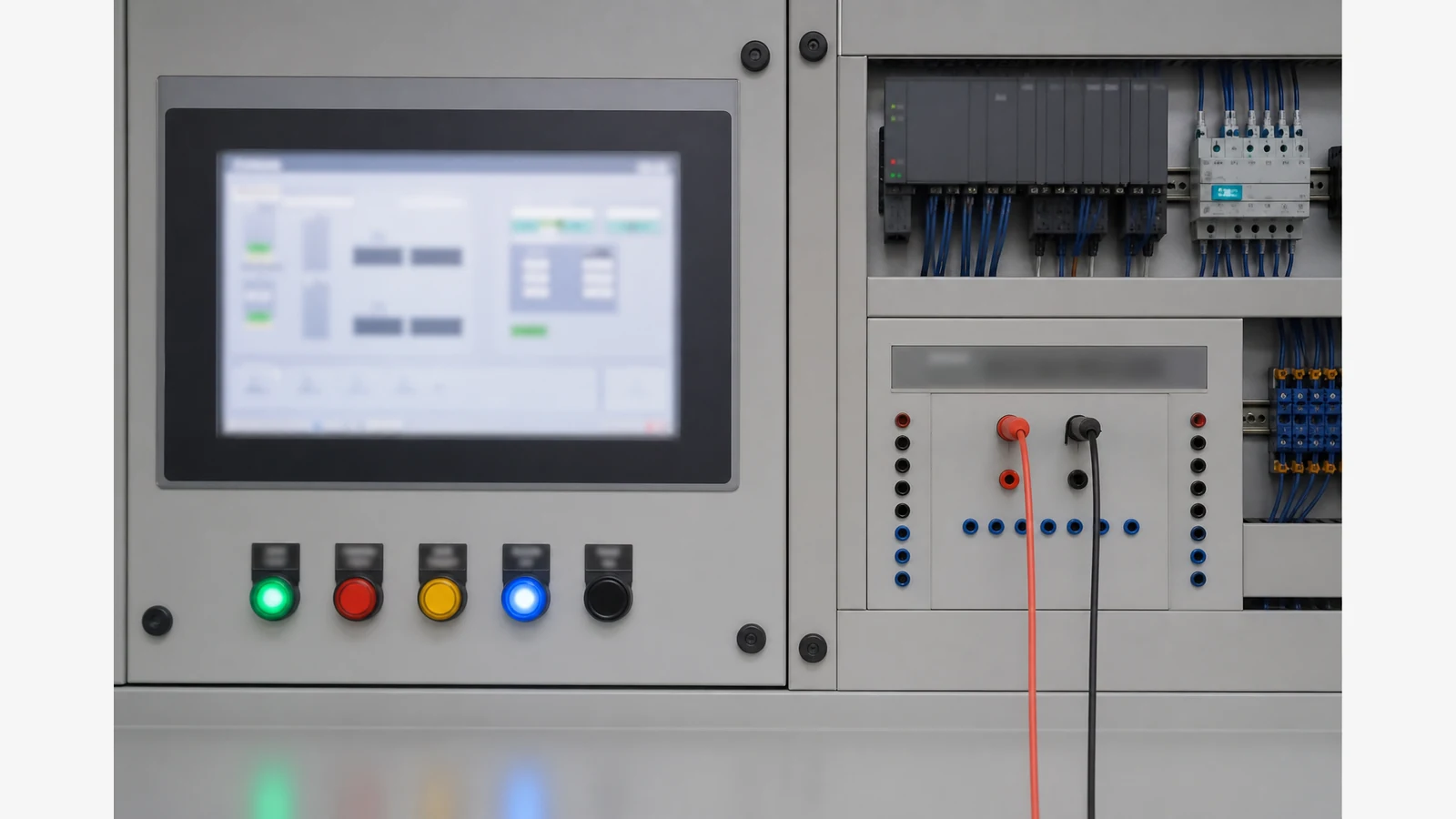
When a UK panel shop must prove 0–10 V analogue input cards before field sensors arrive, inject known voltages at the AI terminals, check HMI scaling, then verify alarm setpoints — do not wait for the transmitter on site. Voltage AI cards need a voltage source; a 4–20 mA loop calibrator alone will not drive a 0–10 V input correctly.
When voltage injection is the right tool
Use voltage simulation for 0–5 V or 0–10 V PLC cards, many HVAC/BMS sensors that output voltage, and FAT benches where sensors are not fitted yet. Keep mA simulation for true current-loop channels. Mixed cabinets often need both modes in one toolkit.
Practical build notes for simple 0–10 V and 4–20 mA simulators, and commercial analogue simulator manuals, describe the same prove idea: inject stepped setpoints and read the controller — see 0–10 V and 4–20 mA simulator methods and the PLC Tools SIM-ALP2 voltage source notes. Cheap pot-divider hacks are fine for rough wiring checks; they are not calibration-grade references.
Panel-shop sequence (0 / 5 / 10 V)
- Isolate: confirm the AI common/grounding scheme; remove or open the field sensor link so you do not back-feed the transmitter.
- Inject 0.00 V: expect scaled zero (or live-zero equivalent if the map starts above 0 V).
- Inject 5.00 V: expect mid-scale engineering units on the HMI.
- Inject 10.00 V: expect full scale; confirm over-range behaviour if configured.
- Alarms: step through any high/low process alarms while the source holds a stable voltage.
- Record: as-found/as-left voltages, HMI values, and who signed the prove sheet.
Confirm card common and earthing before injecting voltage — wrong commons can create ground loops or damage inputs. For milliamp-centric loops, pair this workflow with 4–20 mA signal generator practice and loop calibrator vs multimeter.
Pot divider versus multifunction source
A resistor divider and meter can prove “the wire lands on the right terminal”. A multifunction process signal source with stable voltage output speeds FAT when three technicians share one injector across many channels. Small UK integrators often stock one shared injector for the panel shop rather than one per van.
If your crew still lacks a shared voltage/mA injector for FAT, review options on the Seesii product detail page.