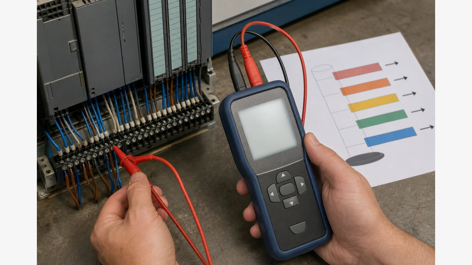
Namur Ne43 Fault Current Bands Plc Setup
Map NAMUR NE43 fault bands on the PLC analogue input so under-range and over-range currents raise an instrument-fault alarm — not a false “process at zero” reading. Live zero on a 4–20 mA loop is 4 mA; currents below about 3.8 mA or above about 20.5 mA sit outside the normal measurement band and are commonly treated as diagnostic fault states.
Measurement band versus fault band
On a standard 4–20 mA input, 4 mA is live zero and 20 mA is full scale. NAMUR NE43-style practice adds fault regions outside that span so a broken wire, failed transmitter, or forced fail-safe current is not mistaken for a genuine process value. Vendor documentation for industrial analogue I/O commonly cites under-range around 3.6 mA and over-range around 21 mA as typical NE43-style fault currents, with a caution band near the edges of the measurement range.
Confirm the exact thresholds in your transmitter manual and PLC card datasheet: manufacturer fail-high or fail-low currents can differ from the 3.6 / 21 mA examples. Do not treat this article as SIL or SIS design guidance; safety instrumented systems need site documentation and competent design review.
- Normal measurement: roughly 4.0–20.0 mA scaled to engineering units.
- Caution / near-limit: often discussed around 3.8–4.0 mA and 20.0–20.5 mA — useful for early warnings, not automatic “fault” labels unless your standard says so.
- Fault under-range / over-range: typically below ~3.6 mA or above ~21 mA when NE43-style bands are applied.
Beckhoff’s analogue I/O guidance summarises NAMUR NE43-style boundaries for process signals, and independent NE43 overviews explain why fault-state currents sit outside the live-zero span — see the Beckhoff NAMUR NE43 boundary notes and this NAMUR NE43 fault-state overview.
Prove under-range and over-range with a milliamp source
After isolation and permit steps, disconnect the field transmitter from the AI channel (or use a test terminal) and inject known currents with a handheld milliamp source:
- Inject 4.00 mA and 20.00 mA — confirm HMI/SCADA engineering units and any process alarms.
- Inject ~3.6 mA — confirm the PLC raises the instrument-fault / under-range diagnostic, not “0% process”.
- Inject ~21 mA — confirm over-range / fail-high diagnostic behaviour.
- Return the loop to the as-found wiring and record as-left currents and alarm states on the I/O list.
If you only have a multimeter, you can measure loop current but you cannot inject a known out-of-band value to prove the PLC logic. A portable source with step or preset mA points makes this prove-out practical during panel SAT. Related field practice for stuck loops is covered in our 4–20 mA loop troubleshooting guide.
UK panel cue before SAT
Document AI fault thresholds on the I/O list before customer SAT: channel tag, scaled range, under-range trip (mA), over-range trip (mA), and which PLC alarm word or diagnostic bit is expected. That single row prevents arguments about whether “3.6 mA should look like zero” on the HMI.
When the kit still lacks a handheld milliamp injector for out-of-band proves, review a multifunction process signal source on the Seesii product detail page.